

 | > E&O/GL Insurance for Home Inspectors Competitive Rates, Broad Coverage, Free Risk Management, online inspection support for tough questions, discounts on education and more… Professional Coverage, Competitive Pricing Shop OREP today! |
Private Water Systems: The Science Behind Your Inspection
By Tom Feiza, Mr. Fix-It, Inc, HowToOperateYourHome.com
Private water/well systems are not part of most standard home inspections. However, you should understand the well system’s basic components, maintenance, and possible repair issues. You should inform homeowners of their responsibilities and liabilities as well owners. If you don’t inspect the water and well system, recommend an evaluation by a specialist.
Since you won’t often see a submersible well pump replacement, here it is—the “big reveal”—replacing a pump. All inspectors should have a basic understanding of these water systems so they can provide basic information during a home inspection.
Private Well Components
Figure 1: Well Pump (Submersible) and Pressure Tank shows a private well system’s basic interior and exterior components. Outside, a submersible pump sits inside a well casing below the water level. The top of the steel casing sits about 12 inches above the soil to keep contaminants out. The “pitless adapter” connects the pump and piping to the underground water supply pipe into the home. The pitless adapter allows the pump and piping to be pulled up from the well casing for repairs.
From the outside to the inside, there is a supply water pipe through the basement wall. Inside the home there is a pressure tank (water storage), sampling valve, main valve(s) and basic controls. This is a simplified illustration and does not show the 240-volt power supply, wiring and switching.
In operation, water flows up from the pump, through a pitless adaptor, and into the home’s pressure/storage tank. Pump controls are located near the tank. The pressure switch is a relay that activates the 240-volt power supply to the centrifugal pump in the water supply in the well casing.
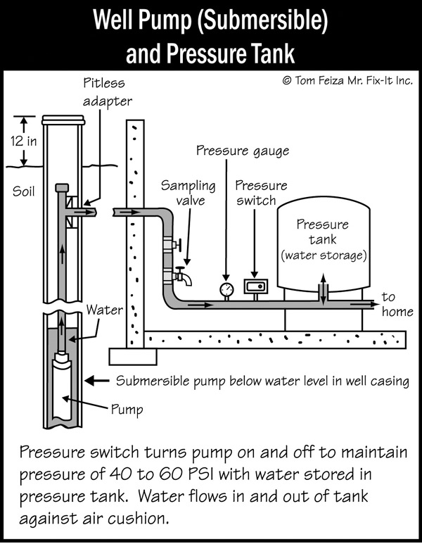
Figure 1: Well Pump (Submersible) and Pressure Tank
What is the Centrifugal Pump?
Figure 2: Centrifugal Pump — Basics represents a typical centrifugal pump and motor. The motor spins the impeller mounted on the motor shaft. Water flows into the center of the impeller (suction) and the centrifugal force of the spinning impeller throws the accelerating water out of the housing at a higher pressure.
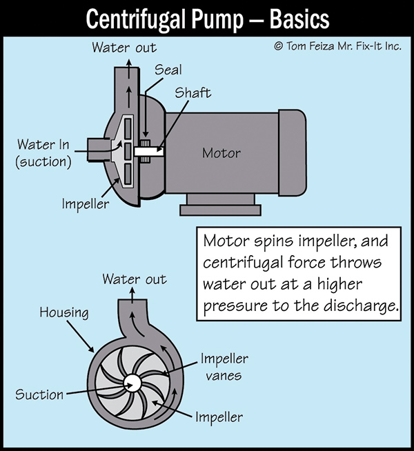
Figure 2: Centrifugal Pump — Basics
Figure 3: Well Pump — Submersible represents a centrifugal submersible well pump. The pump, about four inches in diameter and 30 inches long, has multiple centrifugal impellers attached to an electric motor. The impellers are sized for the well depth and flow requirements. It requires multiple impellers to create enough pressure and flow to push the water to the surface and into the storage tank. With this stacked impeller pump, water flows from impeller to impeller to increase the pressure.
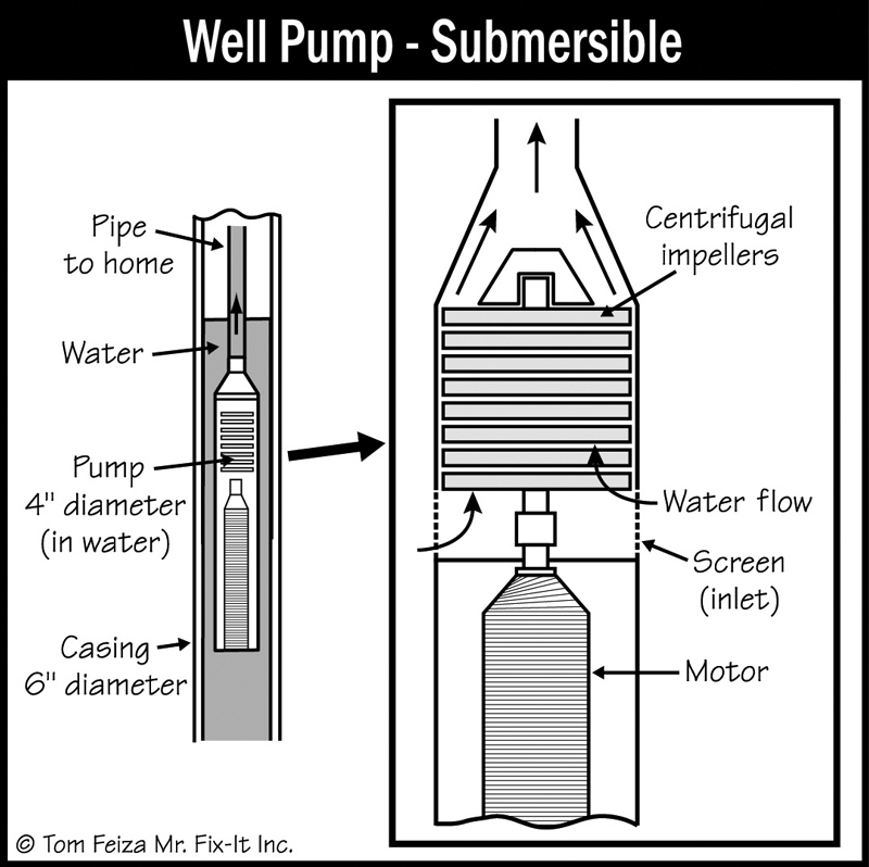
Figure 3: Well Pump — Submersible
Actual Well System
Take a good look at an actual private water system you see in a basement. Like most basements, this system is crowded into a corner and surrounded by storage. The tank is fiberglass and the owner has posted yellow notes describing how to find the water tank and how to turn off the main water valve. The main shut-off ball valve has the yellow handle on the insulated pipe and the handle is parallel to the pipe or in the “on” position (Figure 4: Water Tank and Controls). To the left of the tank, you can see the drain valve at the bottom and the sampling valve for water testing. On the left, the small piping is connected to the pressure control switch (small gray box) and a pressure gauge. At the top left of the tank, mounted on the wall, you can see a 120-volt disconnect switch and a control box for the 240-volt electrical supply to the pump.
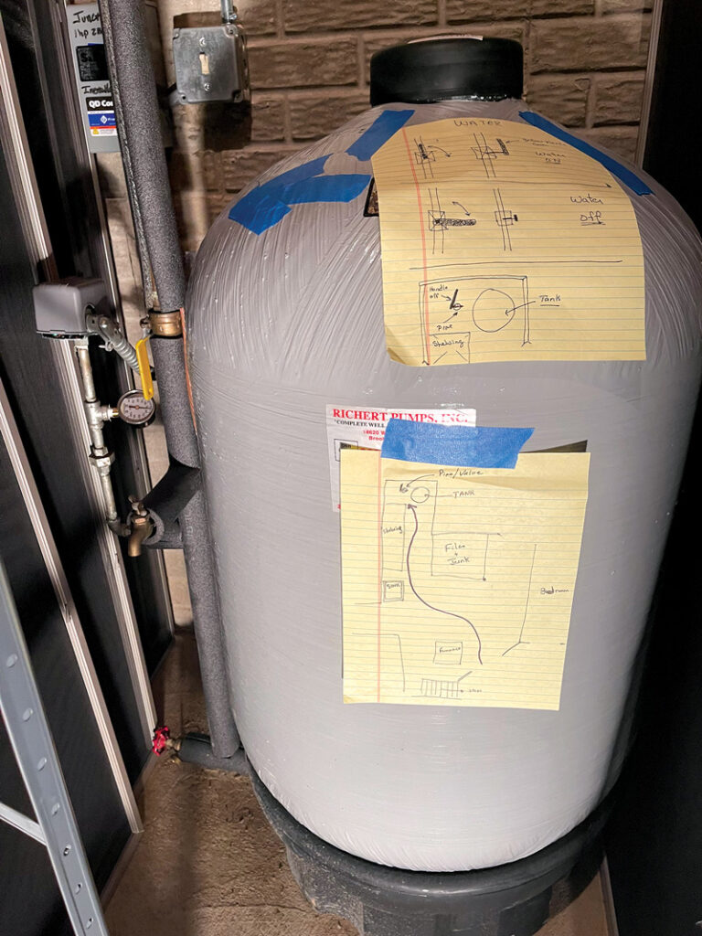
Figure 4: Water Tank and Controls
(story continues below)

(story continues)
Actual Pump and Piping
Figure 5: Pipe, Old Pump, Casing shows an actual well pump being lifted from a well casing for pump replacement—something you rarely see. You can see the top opening of the well casing with the cover removed. Above the casing is the well PVC piping attached to the stainless-steel centrifugal pump. You can’t see the small crane lifting the piping and pump. Attached to the pump and laying on the ground is the 24 0V wiring removed as the pump was lifted from the casing. The fitting just above the pump centers it and transfers torque to the casing. This pump is 24 0V and one HP. It lifts about 25 gallons of water per minute up 125 feet.
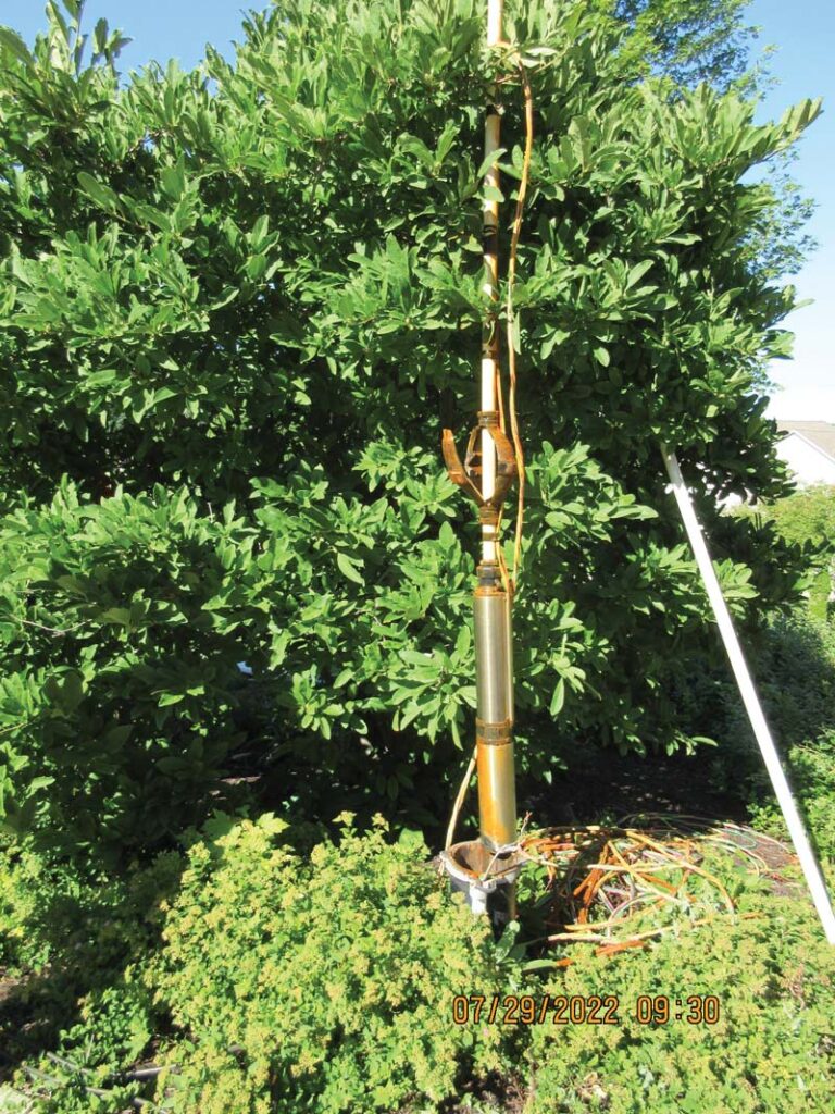
Figure 5: Pipe, Old Pump, Casing
Actual Pitless Adapter and Special Tools
To replace a pump, the plumber removes the well casing cover, then lifts the first section of pipe to expose a device called the pitless adapter, which looks like an upside-down brass trap in Figure 6: Pipe, Pitless Adapter, Orange Clamp. Its name derives from a patent filed in 1953 by Milton B. Martinson for a way of extracting well water without creating a pit, the common practice at that time.
The adapter provides a junction between the drop pipe in the well and the water line running into the house. It enables work on the drop pipe, wire and pump without compromising the existing installation. The plumber screws a T-bar tool or steel pipe into the threaded top of the adapter to remove it (pull it), leaving in place another side piece of the adapter. (In Figure 6 the chrome nipple is screwed into the top of the pitless adapter for lifting.)
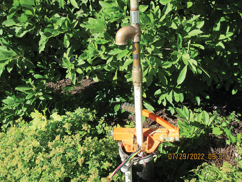
Figure 6: Pipe, Pitless Adapter, Orange Clamp
Also visible in Figure 6 is an orange clamp tool atop the well casing; it holds the pipe between lifts. The pipe is removed in sections as the pump is lifted with the pipe. Several hundred feet of pipe can be removed if needed.
Working Under Pressure
A pressure or storage tank is located in the basement and stores water and prevents the pump from turning on and off every time water is used. There is a compressed air cushion above the water in the tank; it expands and compresses with changes in pressure. As water is used in the home, the air cushion in the tank expands to maintain pressure and force water into the piping (Figure 7: Well Tank with Bladder).
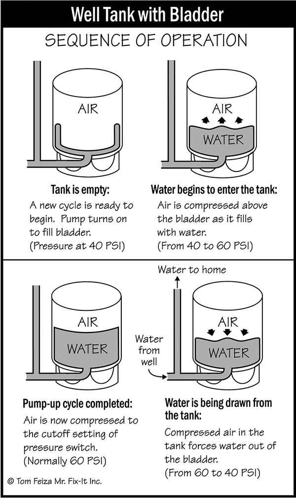
Figure 7: Well Tank with Bladder
The cushion of air generally varies in pressure within a normal operating range of about 40 to 60 pounds per square inch (psi). As water is used, the pressure decreases; when it reaches 40 psi, the automatic pressure sensing switch turns on the electricity to the pump. With the pump running, water is forced into the tank, raising the pressure of the air and water. As the tank is fully recharged with water, the pressure approaches 60 psi, and the pressure switch turns the pump off (Figure 8: Well Tank Pressure Problems).
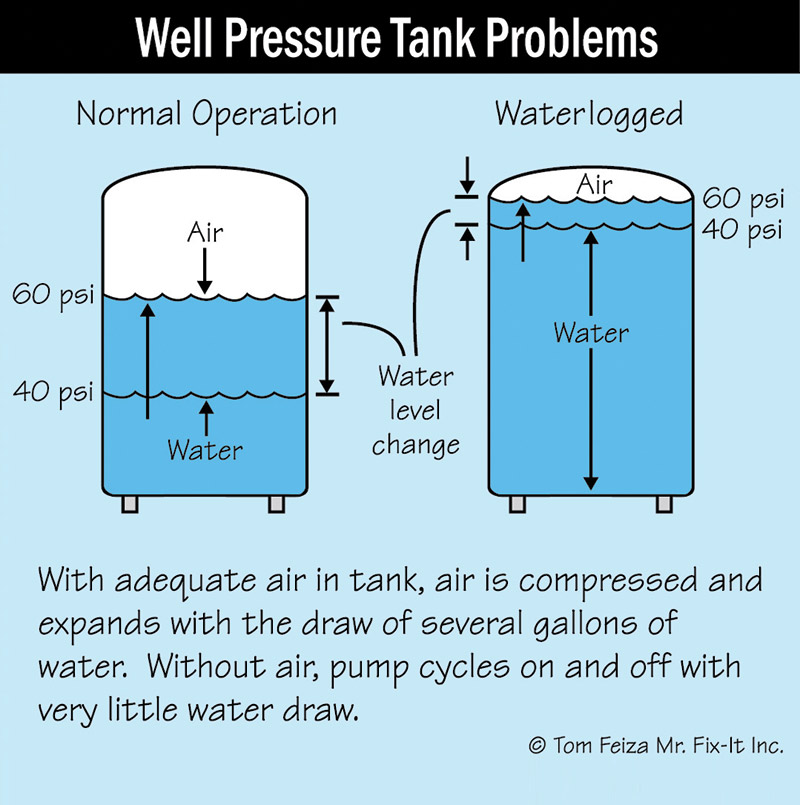
Figure 8: Well Tank Pressure Problems
If a small amount of water is used, the pump will not start; water will be drawn from the tank. The slow pressure changes are barely noticeable in the home.
Spotting a Waterlogged Tank
The most common and damaging problem in a private well system is a waterlogged pressure tank. A tank is waterlogged (full of water) when there is little or no air cushion in the tank.
Without an air cushion, there is no air pressure to push water out of the tank into the home’s piping. The pressure will vary quickly whenever a small amount of water is used.
This quick change in pressure causes the pump to start and stop almost every time water is used. As soon as the pump starts, the pressure will go up very quickly. For instance, if you are running a yard sprinkler, the pump will constantly turn on and off, and you will notice the pressure change at the spray of the sprinkler. If the pump is allowed to continue turning on and off (short-cycling), eventually the pump will be ruined.
You can identify a water-logged tank by quick changes in pressure and how the pump switches on almost every time water is used. A home inspector can easily find this issue by standing next to the pressure tank while running water. You will hear the clicking of the control switch, (the on-off hum of the pump) and see quick changes in the pressure gauge.
The Takeaway
Understanding the components, operation and maintenance of a private well and water system is part of being a great, informed inspector. You may not inspect private well systems, but when you understand the systems, you can inform your customer of their future responsibilities and liability. Many buyers don’t even know they are buying a property with a private well. The new homeowner will need to operate and maintain the well system and you can give them the basic information they need.
Consider providing a reference document that explains the well-system components and operation. Most local health departments provide a free brochure about safely operating a private well system. Also, inform the buyers about any local municipal safety and health requirements related to a private well. Normally, wells require registration with a local authority and routine testing for water safety. At the time of property transfer, the well is often evaluated and the water is tested—you should suggest this be performed.
About the Author
Tom Feiza has been a professional home inspector since 1992 and has a degree in engineering. Through HowToOperateYourHome.com, he provides high-quality marketing materials, books for homeowners, and illustrations that help professional home inspectors educate their customers. Copyright © 2024 by Tom Feiza, Mr. Fix-It, Inc. Reproduced with permission.
Visit HowToOperateYourHome.com for more information about building science, books, articles, marketing, and illustrations for home inspectors. E-mail Tom at Tom@htoyh.com with questions and comments, or phone (262) 303-4884.
OREP Insurance Services, LLC. Calif. License #0K99465