

 | > E&O/GL Insurance for Home Inspectors Competitive Rates, Broad Coverage, Free Risk Management, online inspection support for tough questions, discounts on education and more... Professional Coverage, Competitive Pricing Shop OREP today! |
>> Editor’s Note: To help you stay up-to-date and connected, OREP/Working RE has established a Coronavirus (COVID-19) Discussion and Resource Page where you can share your thoughts, experiences, advice and challenges with fellow inspectors. See what Inspectors are saying here!
Electrical Receptacle Testers Demystified
By Victor G. Faggella, P.E. ACI 107457
One of the major systems that we, as home inspectors, are tasked with examining is the home’s electrical systems. This includes the service entry, the meter enclosure, the service panel and disconnect (or any other panels) as well as the home’s wiring. Of all the parts described, only the wiring is mostly buried in wall and ceiling cavities and cannot be directly examined. For most inspectors, the only way they determine if receptacle outlets are wired “correctly” is via a three-prong cube tester.
This article will attempt to show why using a cube tester—sometimes called a 3-bulb tester (with or without a voltmeter)— only gives part of the story, or can give misleading information as to the condition of the circuits and their adequacy for modern living. Note, this article will not be discussing older, two-wire circuits with no equipment ground (knob & tube and older NM wiring). We will focus on circuits with 3 prong receptacles that should have an equipment ground present.
Why Do We Need to Test?
Why do we even need to test receptacles—there are only three wires? What could possibly go wrong? Anyone who has been an inspector for any length of time is likely chuckling right now, as they know full well what the big-box stores have created with homeowners attempting to do their own wiring.
We need to test receptacles to ensure:
• Proper Polarity
• Presence of an equipment grounding conductor (EGC)
• Proper voltage (ideally under some defined load)
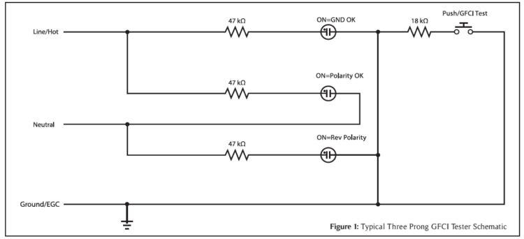
Of the three items above, simple cube testers can only perform the first function reliably. To understand this, you need to understand what is actually inside a common three-light receptacle tester. See Figure 1 above.
As can be seen from Figure 1, there are just three neon bulbs wired as follows (and a push button):
• Hot-Ground
• Hot-Neutral
• Neutral-Ground
Under “normal” circumstances, the first two lights will illuminate and the last one will be off. Under reversed polarity (ONLY Hot-Neutral reversed), only the third light will illuminate. Now, with an open ground, only one light may illuminate, if the polarity is correct. With an open ground, and reversed polarity, you will get no lights. If you happen to have 240Vac somehow, all three lights may be on. Confusing, right? Now, it is beyond the Standards of Practice in most places to determine what the problem is—we just need to state that there is one. But having been in the business for over 33 years and being an electrical engineer, I personally need to know what the possible issues are.
Shortcomings of Cube Testers
As you may have already figured out, cube testers can’t tell you everything about the way a standard three-prong receptacle is wired. It can’t tell you if there is a false (aka “bootleg”) ground (more on this later) or anything having to do with the voltage actually present at the receptacle, much less the voltage when an appliance is plugged in and drawing power.
For you, the inspector, to be able to share better and more complete information concerning the condition of a mostly “out of sight, out of mind” system, is, in my opinion, paramount to your clients. Deficiencies in a structure’s wiring can lead to erroneous operation of equipment, damage to equipment, a shock hazard to residents, and even a potential for a fire. (Remember: ALWAYS use the test button on the GFCI/AFCI device as this is the only recognized test.)
Circuit Analyzers
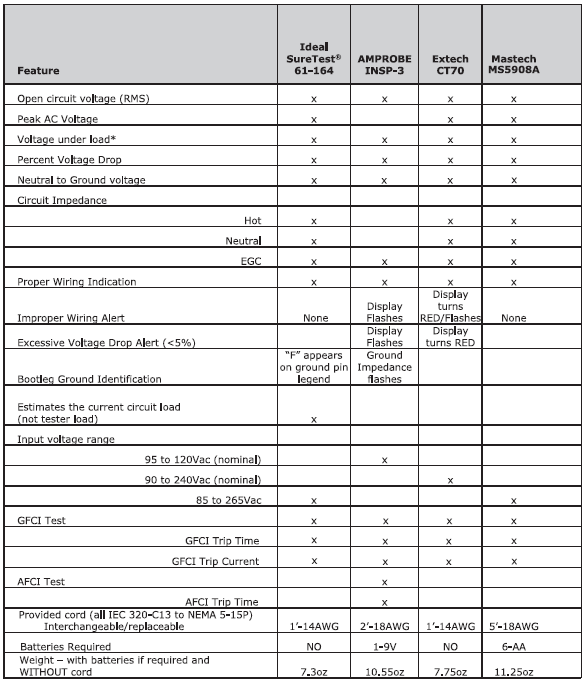
There has been a logical progression from cube testers, to cube testers with voltmeters, to full-blown circuit analyzers over the years. Circuit analyzers will show open circuit voltage, loaded voltage (See Figure 2, pg. 36), line frequency, line impedance (H-N-G) and other unique features. These full-blown analyzers can be had for as little as just over $10 0 on Amazon for a generic, “no-name” Mastech brand, to $20 0 for an Extech CT70, to close to $400 for the Ideal SureTest® 61-164 and the Amprobe INSP- 3.
The remainder of this article will go over the real-life performance of each of these compared to the others so you, as an inspector, can make an intelligent decision as to which one, if any, makes sense to add to your equipment arsenal. (Links to where you can purchase these items may be found online at www.workingre.com/electrical-receptacle-testers-demystified.)
Ideal SureTest® 61-164
Full Disclosure, Ideal Industries provided this unit for me to test as part of this article. But this in no way will taint my review of the analyzer.
The SureTest® 61-164 is the lightest of the bunch, at just over 7 oz. It comes with a very stiff, high quality 1′-14AGW cord. The display is bright yellow and is easily readable in most lighting conditions, but is unreadable in full, bright, sunlight outdoors. Shield the display with your hand and it will be legible.
The feature set is rich. Only one parameter is displayed at a time, and other features are selected by the use of the right and down arrow buttons. The right arrow will scroll through all the choices for the available subfunctions and then it will return back to the first choice. Likewise, for the down arrow. Each press takes you to the next major function and then returns you to the top choice (power-on state) once you scroll to the bottom. If you scroll past what you wanted to look at, you need to scroll all the way through. Not a big deal, as most of us will go one function at a time and then look at each parameter under that main function.
The default power-on reading is the polarity. Note that it takes about 5–6 seconds to give you a reading each time it is plugged into a receptacle. This is the longest of any of the testers in this article. A legend on the back of the case shows the meaning of the display. The SureTest® uniquely identifies a false/bootleg ground by illuminating the ground pin legend with an “F” in the center. This feature, however, is not 100% accurate. It will NOT identify a false ground on runs that are relatively short and close to the load center. The representative from Ideal Industries was very up front about this. Any circuit under 20–3 0 feet in length will have such a low impedance that the device cannot accurately determine proper from false equipment ground.
The second main menu item is for reading the voltage-RMS (H/N & G/N), peak voltage and frequency. The value is clearly displayed in the center with the parameter on the bottom of the display. The only downside is if the brightness between the selected and unselected parameters isn’t that great. It would have been better if only the selected parameter was illuminated, but this is a minor criticism.
The third main menu item down is voltage drop. The default load is 15A. Pressing the right button selects a load of 20A, pressing it again selects 12A and pressing the right arrow once again returns to the 15A default load. The voltage under the selected load is displayed at the top and the percentage drop in the center and the selected load is displayed at the bottom. The display does NOT blink or change in any way to indicate what some might consider excessive voltage drop. You will have to make your own decision here.
The fourth item on the main menu is amperage. The SureTest® has a function that is unique amongst those here, and that is Estimated Line Load (ELL on the display). This feature displays the estimated load already on the circuit under test. This is very useful, especially if you are getting voltage readings that are lower than other circuits that have been tested. A large load may cause a lower voltage reading and give misleading voltages under the 12, 15 and 20 ampere test loads.
The fifth and last main menu item is circuit impedance—the impedance of all three wires can be measured—the line/hot, the neutral and the ground (EGC). One thing to note is that if you try to measure the EGC impedance on a GFCI protected circuit, you will trip the GFCI. The right arrow moved the default selection from hot, to neutral to ground and back to hot, like all the other submenus.
The last function that is standalone from the menus is the GFCI test. There is large oval button labeled “GFCI” right under the down and right arrow keys. Pressing this button at any time brings up the GFCI test window. This window defaults to “GFCI” and the estimated test current in mA (approximately 7mA). Pressing the right arrow will toggle to the “EPD” test with an estimated test current in mA (approximately 30mA). Pressing the “GFCI” button again will initiate the test. After the GFCI trips and is reset (with the tester still plugged in), the GFCI trip time in milliseconds and the actual trip current will be displayed.
(story continues below)

Amprobe INSP-3
I reached out to Amprobe for this article and never heard back. The one tested is one I personally purchased and have used for several years. The Amprobe INSP- 3 requires a single 9V battery to operate properly. The need for an auxiliary power source will become evident as we go through the features.
The INSP- 3 is the second heaviest of the lot at just over 10.5 oz. It comes with a 2′-18AWG cord that is very flexible. The extra length can come in handy at times, but is a pain to store in the tool belt. The INSP- 3 has a large dot matrix LCD display (the largest in here) that is visible even under direct sunlight outside. When the unit is first plugged in, it takes about 3 seconds for the information to be displayed.
The main display contains nearly all the information about the circuit under test on the first screen. The RMS voltage and frequency are displayed on the top line. The next line is the polarity—OK, No Ground or Hot/Neutral Reversed (VERIFY DISPLAY) The next line is the percentage voltage drop at the selected load (independent buttons below the display). The percentage figure will blink when the value exceeds 6 percent. (VERIFY DISPLAY) The next line is the percentage drop on the hot and neutral separately that add up to the total percentage shown on the line above.
This is helpful for tracking down where the issue might be if not evenly split. The next line is the actual loaded voltage and the bottom line is the ground impedance. There are no separate measurements displayed for the line/hot and neutral impedances. The ground impedance value will blink if the value is excessively low. I do not know if this is measured against the neutral impedance in any way, so its utility to find false/bootleg grounds is unknown.
Pressing the Power/Select button once brings up the second screen. The top two lines are the same as the first screen, RMS voltage, frequency and polarity. The next line is common mode voltage—voltage from ground to neutral, and short-circuit currents: “HotNeu Fault” and “HotGnd Fault”. These are the maximum currents calculated using the circuit impedance. (In theory, knowing the ground impedance and the fault current you could figure out the line/hot impedance. Knowing the line/hot impedance now, you could use that fault current to figure out the neutral impedance. Not worth it for me).
The INSP- 3 has the ability to test both GFCI AND AFCI devices. The only caveat is that you must press the GFCI or AFCI test button before the tester is plugged in. Failure to do so will cause the GFCI or AFCI device to malfunction before any data is displayed. To perform a GFCI breaker test remotely, the “GFCI Test: button and the unit will turn on and prompt you to plug the unit it when it is ready. All the same data as before is displayed except the ground impedance (remember what happened with the SureTest® when we tried to test ground impedance on a GFCI circuit?). The unit displays a blinking “Press GFCI button to trip” where the ground impedance line was. To perform the trip test, press the applicable button again and the test will run. The results are displayed on the screen. (This is why an external battery is required).
The AFCI test is similar. You must know it’s an AFCI circuit and press the “AFCI Test” button and wait for the prompt before you plug in the tester. With AFCI circuits becoming the norm on many circuits, this will become a major inconvenience when using the device. It is also known that it does not work with certain Bryant (Eaton) breakers and with the constantly changing AFCI technology, this feature is not useful and is likely a negative for this unit. From experience, it can be a pain when there is a GFCI on a circuit you are not expecting (like my living room) and you plug in the tester and the GFCI trips.
One final negative of the INSP- 3 is that it has an internal fuse that is NOT USER REPLACEABLE. This means that when it blows (and it will blow based on the forums) you have a unit that doesn’t work and has to be sent back to Amprobe for repair. I opened up my unit to fix it and couldn’t get the proper fuse to replace it (I was going to put a fuse holder in to make it easier to repair in the future but gave up). I soldered a single strand of 28-gauge wire across the fuse and it has been good for a year or more since. Just a poor design.
Extech CT70
The Extech CT70 comes in at about half the price of the Ideal and Amprobe testers. Let us see what it has to offer.
The CT70 is the second lightest in the group at 7. 75 oz. It comes with a 1′-14AWG cord that is almost identical to the one that came with the SureTest®. When the unit is first plugged in, it takes about 3 seconds for the information to be displayed.
The main display is large and normally has light blue values on a dark blue screen. The main screen contains a polarity indication on the top right, with the RMS voltage in the center and the frequency at the bottom. The top left has the same main menu items as the SureTest® (V, Vd, Z and ASCC). The controls are the same as the SureTest®, with a down and right arrow keys and a GFCI button.
Pressing the right arrow on the main voltage screen changes the polarity screen to show N/G voltage, while still showing the frequency. Pressing the right arrow again changes the polarity screen back to normal and shows the peak voltage and the frequency. One last press and you are back to the power-up screen.
Pressing the down arrow brings up the voltage drop screen. The polarity is still displayed at the top. The voltage under load is displayed in the center and the percentage drop is displayed beneath it. The CT70 is unique in that the entire display changes to bright red values on a darker red background when the voltage drop gets to 5% or greater. The right arrow cycles through the load choices, starting at a default of 15A, then 20A, 12A and then back to 15A.
Pressing the down arrow again brings us to the impedance measurement screen. What was the polarity indication changes to display a “H” only, and continues to display the RMS voltage with the circuit impedance on the bottom. Pressing the right-arrow once will change the top display to a “N” display the neutral impedance at the bottom. If you try to measure the ground impedance on a GFCI protected circuit, you should have figured out by now that the GFCI will trip, so be careful! One last press of the down-arrow brings up the ASCC (short-circuit current) screen. The first screen shows the H-N short circuit current in kA. Most of the time this will be less than 1. The number displayed to the right of the decimal point is just amperes, so 0.350kA is 350A. Press the right arrow and this brings ground into the circuit. And guess what? Try this on a GFCI protected circuit and it will trip, so don’t be surprised.
The last function that is standalone from the menus is the GFCI test. There is large red button labeled “GFCI” right between the down and right arrow keys. Pressing this button at any time brings up the GFCI test window. This window defaults to “GFCI” and the estimated test current in mA (approximately 7mA). Pressing the right arrow with toggle to the “EPD” test with and estimated test current in mA (approximately 30mA). Pressing the “GFCI” button again will initiate the test. After the GFCI trips and is reset (with the tester still plugged in), the GFCI trip time in milliseconds and the actual trip current will be displayed. This is nearly identical to the SureTest® on look, feel and functionality.
Mastech MS5908A
This tester is the heaviest of the group at 11.25 oz. It comes with a crazy long 18 AWG cord that is 5 feet long. It also the only tester that must be turned on before you plug it in. It will time out and shut off after 30 minutes of idle time (a feature you can override at power-up). It also has this annoying beep every time you press a button that cannot be turned off.
The MS5908A is also the only tester that must be turned on with the power button before you can test anything. It takes less than one second for the display to come up. The default is with the backlight off. The button on the bottom left activates the backlight, which stays on for approximately 20 seconds and then turns off again, presumably to save battery power.
The main screen starts with the voltage displayed and shows the line frequency at the top right, the RMS voltage (L-N) in the center and the wiring legend at the top right along with the energized/power symbol (these are present on all function menus). Down the left side shows what voltage is being displayed: L-N, N-E or Peak voltage. The values are large and easy to read (LCD display) and the backlight is very effective in EL green.
There are two yellow buttons on the right side. Pressing them with cycle to the next menu choice withing a function (displayed along the bottom of the screen with the selected function surrounded by a box). This allows the user to go back and forth from L-N to N-E and back without cycling through all the options. Below the yellow arrow buttons is the TEST button. On the left side are the power button, the FUNC (function) button, the HOLD button and at the bottom the backlight button.
Pressing the FUNC button once and the unit goes to the Voltage drop (Vd) menu. When first entering this function, the display just shows lines. This is where the TEST button comes in. Pressing the TEST button shows the line voltage under load, the load in small type in the center and the voltage drop percentage at the bottom in large type. The Yellow arrow buttons cycle from 12A to 15A to 20A and back again (the default is 12A when you enter the function, regardless of what it was if you cycle through the functions). Here you can go back and forth without cycling through the three choices. The display doesn’t change if there is any excess voltage drop like the Amprobe and Extech do.
Pressing the FUNC button again brings you the Z (impedance) menu. The frequency will display at the top right and Z-L will show along the left side. The main display is lined out until TEST is pressed. Pressing the down Yellow arrow buttons will show the Z-N and Z-E impedances. When you get to the Z-E selection, you need to press the TEST button again. Be aware that if you do this on a GFCI protected circuit, it will trip the GFCI and you will not get any results. At least all the testers are consistent when it comes to this. If you press the down Yellow arrow button again display ASCC (available short-circuit current). You may have to press the “test” button if you haven’t yet in the function menu.
The last two functions are for GFCI functions. The first is RCD (residual-current device and has the same 30mA test as EPD). Pressing the TEST button will test at approximately 30mA and the actual test current and trip time will be displayed. If you press the FUNC button to get to the GFCI menu, and press TEST, the actual test current (approximately 7mA) and trip time will be displayed.
Overall Impressions
There were some surprises in this comparison. Below are my detailed impressions of each tester, and at the end I will rank them by feature and then by value.
The SureTest® 61-164 is feature-packed. It has the most complete set of functions of any of the testers. I have issues with the small display that is unreadable in direct sunlight. It also takes a long time to boot up when plugged in, which will add to your inspection time if you check all the receptacles (as I do). It is the only tester to explicitly flag a False/Bootleg ground and the only one to estimate the existing load on a line to put the voltage readings in perspective. One negative is that if you take pictures of the display for your reports, the refresh rate is slow and you may not get the entire display. This was very frustrating. It currently retails for just over $360 on Amazon (although IDEAL Industries did donate this for this comparison).
I have used the Amprobe INSP-3 for several years and never realized that it didn’t have the Hot and Neutral impedances available to display. Now almost $450 on Amazon, I was surprised and the features it lacked when compared to the SureTest® 61-164, especially the lack of Hot & Neutral impedance measurements. There was only GFCI testing and no selection for RCD/EPD selection (30mA). While not needed for home inspections, it a feature that could have easily been added. In addition, the INSP-3 falls short, requiring the user to push the GFCI/AFCI test button BEFORE plugging the device in. Just impractical with more and more circuits being GFCI and/or AFCI protected, and it requires a 9V battery to boot.
The Extech CT70 performed very well overall. One area it fell short was the impedance measurements. Most were low compared to all the other testers and the ground impedance was very low—read zero—sometimes. I even swapped power cords to be sure and no change. Maybe it’s a defective unit, but I do not know. The display was bright and changed colors with problems, making it easy to find problems, however the display was hard to photograph due to the limited viewing angle. With practice, you will get quality pictures for your report. At just around $200 on Amazon, it’s about half the price of the other “big boy” testers—but it’s the only one of the four that didn’t come with its own case.
The Mastech MS5908A was the sleeper in this group. It consistently produced readings that were nearly identical to that of the SureTest® 61-164, which was very surprising to me. It is fairly intuitive to use, has a large display and can be backlit when required. The drawbacks are it requires six AA batteries; the cord is just way too long and that beeper on every button press was annoying. For just $100 on Amazon, it is by far the cheapest of the group, but how long it will last is up for debate.
Overall Winner
Overall, for the features provided and the two-year warranty, the SureTest® 61-164 takes the win despite its high price. It is manufactured by a reputable US-based company that specializes in industrial test equipment and stands behind its products. It is expensive, though, so if you want to try one of these without breaking the bank, try the Value Winner.
Value Winner
The ringer in this group was the Mastech MS5908A. It matched the SureTest® 61-164 for accuracy and provided 99% of the functionality for 28% of the price—you could buy almost 4 of these for the price of a single SureTest® 61-164. I have no reservation recommending this unit if you are short on cash or just do not want to invest a lot into a tester. I plan on using this one and seeing how it holds up over time.
The Losers
The Amprobe INSP-3 disappointed me the most. I am the most familiar with this one and I didn’t know how much it didn’t do. Being the most expensive in the group, I cannot recommend wasting money on it. Coupled with the fuse issue discussed earlier, it’s a swing and a miss for me.
The Extech CT70 held promise. Its voltage readings were consistently higher than the SureTest® 61-164 and Mastech MS5908A, but were within the margin of error (less than 1% off). Where it falls short is the impedance measurements. While the Hot and Neutral readings were close to the others, the ground reading was almost always zero. When the other conductors are measuring 0.2-0.4Ω, there is no way the ground impedance can be zero or even 0.03Ω. This unit offers nothing over Mastech MS5908A other than it’s twice the price and has no case included.
About the Author
Victor G. Faggella has a BS ECE from Clarkson College of Technology (now Clarkson University) and has been a licensed professional electrical engineer and home inspector for over 30 years. He is an ASHI Certified Inspector, who received multiple awards. His engineering experience includes 25 years of instrumentation and control design for nuclear naval vessels. He is “semi-retired” and enjoys time with his granddaughters and helping his son coach baseball.
OREP/WRE Coronavirus Discussion and Resource Page
Coronavirus: National Home Inspector Survey
Real-Life Inspector Lawsuits and How to Protect Yourself
Available Now
Presenter: Isaac Peck, President of OREP
Isaac Peck, President of OREP Insurance Services, shares his insights and advice gained over nearly 10 years of providing risk management and E&O insurance for home inspectors. You will not hear many of these insights anywhere else.
Watch Now!
Send your story submission/idea to the Editor:
isaac@orep.org
Note: The Summer 2022 Working RE Home Inspector is now mailing to over 25,000 home inspectors nationwide. OREP Insureds/members enjoy guaranteed delivery of each print magazine and many more benefits.
by Barry Niemuth
Hello!
-I stumbled onto this article when researching a backup to the Extech CT70 that I’ve used the last five years. I found the Mastech MS5908A online some time back (I believe it was on alibaba) and have considered getting one to try. I’m curious how it’s performed for you in the year plus since you wrote this article. Thanks!
by Robert Moylan Kenney
In your article, “Electrical Testers Demystified,” author Victor Faggella has made an obvious error about the operation of three light testers. He says, “With an open ground, and reversed polarity, you will get no lights.” This is not true. The tester cannot identify reversed polarity unless the ground is also present to light the reversed polarity bulb. The tester will indicate an open ground but not reversed polarity. In fact, this is one of the shortcomings of a three bulb tester. It can only indicate ONE problem at a time. Outlets that have multiple wiring problems will only be identified as having one by the three light tester.
Mr. Faggella did introduce himself as an electrical engineer so he could have done better.
Sincerely,
-Bob Kenney, CMI
Md. License #31044
rkenney74@comcast.net
by Victor G. Faggella, P.E.
You know, you are correct. Somehow when I wrote this, all saw were LEDs and not neon bulbs. Something that was missed-and this was peer reviewed.
Obviously, the neon bulbs will light with reveresed polarity and will only show the ground is open and not reversed polarity. Thanks for catching that.
-